The figure illustrates a deterministic finite automaton using a state diagram. In this example automaton, there are three states: S0, S1, and S2 (denoted graphically by circles). The automaton takes a finite sequence of 0s and 1s as input. For each state, there is a transition arrow leading out to a next state for both 0 and 1. Upon reading a symbol, a DFA jumps deterministically from one state to another by following the transition arrow. For example, if the automaton is currently in state S0 and the current input symbol is 1, then it deterministically jumps to state S1. A DFA has a start state (denoted graphically by an arrow coming in from nowhere) where computations begin, and a set of accept states (denoted graphically by a double circle) which help define when a computation is successful.

An example of a deterministic finite automaton that accepts only binary numbers that are multiples of 3. The state S0 is both the start state and an accept state.
A DFA can be represented by a 5-tuple (Q, ∑, δ, q0, F) where
-> Q is a finite set of states.
-> ∑ is a finite set of symbols called the alphabet.
-> δ is the transition function where δ: Q × ∑ → Q
-> q0 is the initial state from where any input is processed (q0 ∈ Q).
-> F is a set of final state/states of Q (F ⊆ Q).
A DFA is represented by digraphs called state diagram.
The vertices represent the states.
The arcs labeled with an input alphabet show the transitions.
The initial state is denoted by an empty single incoming arc.
The final state is indicated by double circles.
->Write a input.(01001010 etc.)
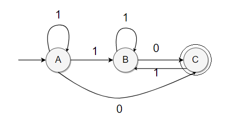
| 0 | 1 | |
|---|---|---|
| >A | A | B |
| B | C | B |
| *C | A | B |
> : Start state
* : Finish state